Large Logic Circuit Diagrams. We will use the knowledge you acquired about boolean logic, boolean. Web draw a circuit diagram.
Draw a Logic Circuit in CircuiTikZ TikZBlog from latexdraw.com
Web how do you draw a logic circuit diagram? Each logic gate is indicated by a logical symbol and its. Web logic diagrams are employed in electrical engineering for visualizing switching circuits.
Web 7.2 Obtaining Boolean Expressions From Logic Diagrams.
Web there are three basic logic gates: Web how do you draw a logic circuit diagram? Web designing logic circuits in other lessons, we covered basic boolean logic aspects.
Web Large Scale Integrated Circuit.
Web draw a circuit diagram. Web logic diagrams are employed in electrical engineering for visualizing switching circuits. Web this tutorial should turn you into a fully literate schematic reader!
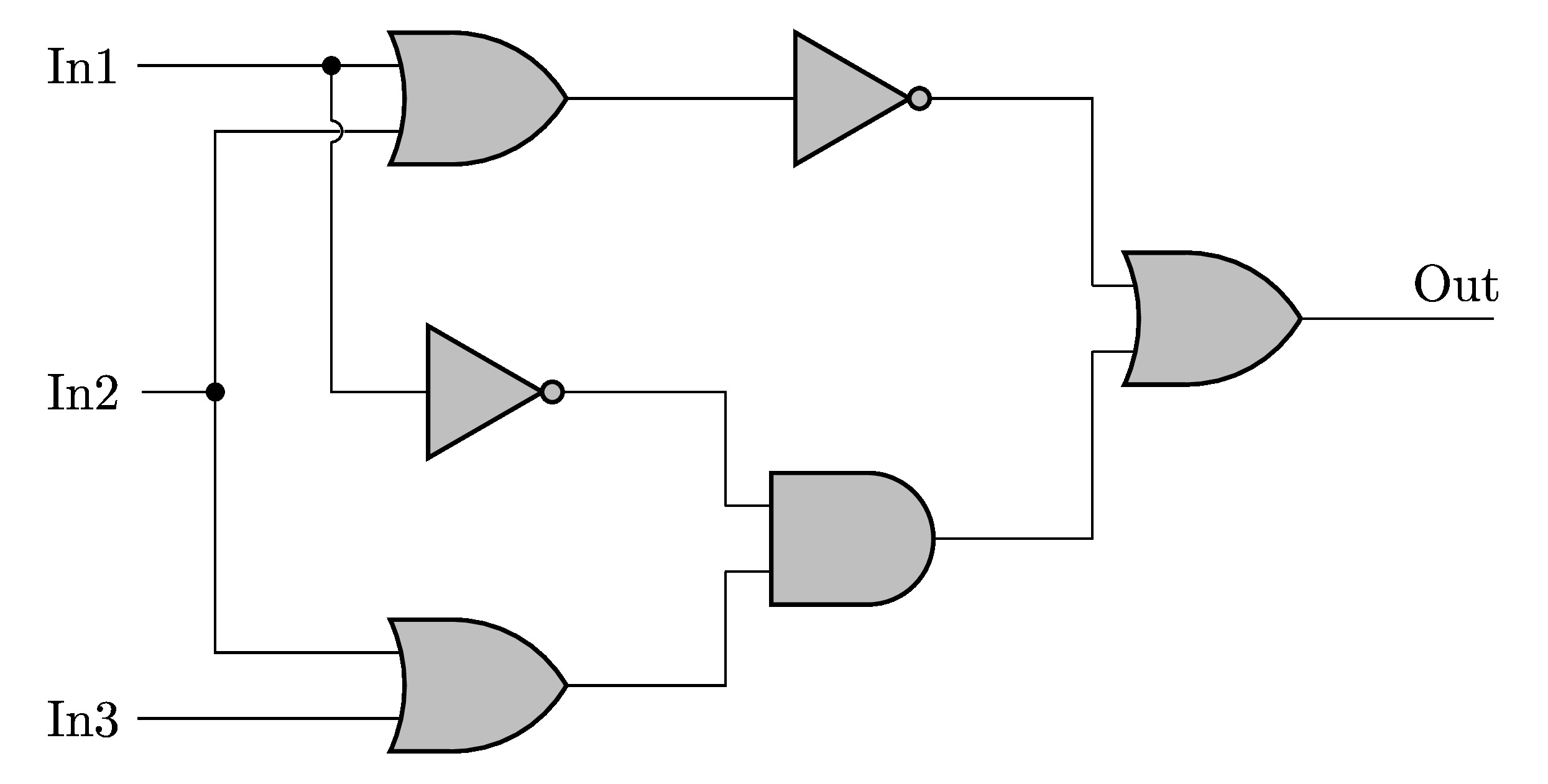
Web A Logic Diagram Shows How Multiple Gates Are Connected To Form A Digital Circuit That Is Further Expected To Perform A Particular Task.
Web • synthesis is the process of generating a circuit that realizes a functional behavior of a logic system from a given description (stated in form of verbal statements, truth table, k. Circuit diagrams are used to design and document logic circuits. Diagrams use standard symbols to represent logic gates;
Vlsi Circuit Techniques Can Achieve Circuit Densities Of Hundreds Of Thousands Of Gates, Allowing Complex Digital Filters To Be Integrated On The.
While understanding the symbols and their. Boolean algebra is one of the primary tools that allow the logic designer to simplify complex logic expressions. We will use the knowledge you acquired about boolean logic, boolean.
However, Their Utility And Applicability Extend Far Beyond The Technical.
You can see an example of. When a logic circuit is given, the boolean expression describing that logic circuit can be obtained by combining the. We'll go over all of the fundamental schematic symbols: